Edm Wire Cut Time Calculation Formula In Excel Free Download
An electrical belch motorcar
Electric discharge machining (EDM), too known as spark machining, spark eroding, die sinking, wire burning or wire erosion, is a metal fabrication procedure whereby a desired shape is obtained by using electrical discharges (sparks).[1] Cloth is removed from the piece of work slice by a series of rapidly recurring current discharges between two electrodes, separated by a dielectric liquid and field of study to an electric voltage. One of the electrodes is called the tool-electrode, or simply the tool or electrode, while the other is called the workpiece-electrode, or work piece. The process depends upon the tool and work piece not making physical contact.
When the voltage between the two electrodes is increased, the intensity of the electrical field in the book betwixt the electrodes becomes greater, causing dielectric break down of the liquid, and produces an electric arc. As a issue, material is removed from the electrodes. One time the current stops (or is stopped, depending on the blazon of generator), new liquid dielectric is conveyed into the inter-electrode volume, enabling the solid particles (debris) to exist carried abroad and the insulating properties of the dielectric to be restored. Adding new liquid dielectric in the inter-electrode book is usually referred to as flushing. After a electric current menstruum, the voltage between the electrodes is restored to what information technology was before the breakdown, then that a new liquid dielectric breakup tin occur to repeat the cycle.
History [edit]
The erosive effect of electrical discharges was first noted in 1770 past English physicist Joseph Priestley.
Die-sink EDM [edit]
Two Russian scientists, B. R. Lazarenko and N. I. Lazarenko, were tasked in 1943 to investigate ways of preventing the erosion of tungsten electrical contacts due to sparking. They failed in this task but found that the erosion was more precisely controlled if the electrodes were immersed in a dielectric fluid. This led them to invent an EDM machine used for working difficult-to-automobile materials such as tungsten. The Lazarenkos' machine is known as an R-C-blazon motorcar, after the resistor–capacitor circuit (RC circuit) used to charge the electrodes.[2] [3] [4] [5]
Simultaneously but independently, an American team, Harold Stark, Victor Harding, and Jack Beaver, developed an EDM machine for removing broken drills and taps from aluminium castings.[6] Initially amalgam their machines from under-powered electric-etching tools, they were not very successful. But more than powerful sparking units, combined with automatic spark repetition and fluid replacement with an electromagnetic interrupter arrangement produced practical machines. Stark, Harding, and Beaver's machines were able to produce lx sparks per second. Afterwards machines based on their design used vacuum tube circuits that were able to produce thousands of sparks per second, significantly increasing the speed of cutting.[7]
Wire-cutting EDM [edit]
The wire-cut type of machine arose in the 1960s for making tools (dies) from hardened steel. The tool electrode in wire EDM is simply a wire. To avoid the erosion of the wire causing information technology to break, the wire is wound between two spools so that the active office of the wire is constantly changing. The earliest numerical controlled (NC) machines were conversions of punched-tape vertical milling machines. The first commercially bachelor NC machine built as a wire-cut EDM machine was manufactured in the USSR in 1967. Machines that could optically follow lines on a chief drawing were developed past David H. Dulebohn's grouping in the 1960s at Andrew Applied science Company[8] for milling and grinding machines. Main drawings were later produced past computer numerical controlled (CNC) plotters for greater accuracy. A wire-cut EDM auto using the CNC drawing plotter and optical line follower techniques was produced in 1974. Dulebohn later used the same plotter CNC program to directly control the EDM motorcar, and the first CNC EDM car was produced in 1976.[9]
Commercial wire EDM capability and use has advanced substantially during contempo decades.[10] Feed rates take increased[ten] and surface cease can exist finely controlled.[10]
Generalities [edit]

1 Pulse generator (DC). 2 Workpiece. 3 Fixture. iv dielectric fluid. 5 Pump. 6 Filter. 7 Tool holder. 8 Spark. nine Tool.
Electrical discharge machining is a machining method primarily used for hard metals or those that would be very difficult to machine with traditional techniques. EDM typically works with materials that are electrically conductive, although methods have besides been proposed for using EDM to machine insulating ceramics.[11] [12] EDM can cut intricate contours or cavities in pre-hardened steel without the need for heat handling to soften and re-harden them. This method can be used with whatever other metal or metal alloy such as titanium, hastelloy, kovar, and inconel. Also, applications of this process to shape polycrystalline diamond tools have been reported.[xiii]
EDM is often included in the "non-traditional" or "non-conventional" group of machining methods together with processes such as electrochemical machining (ECM), water jet cutting (WJ, AWJ), laser cutting and reverse to the "conventional" grouping (turning, milling, grinding, drilling and any other process whose textile removal mechanism is substantially based on mechanical forces).[14]
Ideally, EDM tin can be seen as a series of breakup and restoration of the liquid dielectric in-betwixt the electrodes. However, caution should be exerted in considering such a statement because it is an idealized model of the process, introduced to describe the central ideas underlying the process. All the same, whatsoever practical awarding involves many aspects that may also need to be considered. For instance, the removal of the droppings from the inter-electrode book is likely to be always partial. Thus the electric properties of the dielectric in the inter-electrodes volume tin can exist different from their nominal values and can even vary with fourth dimension. The inter-electrode distance, oftentimes also referred to as spark-gap, is the result of the command algorithms of the specific machine used. The command of such a distance appears logically to be central to this process. Likewise, non all of the current between the dielectric is of the ideal type described above: the spark-gap can be curt-circuited by the debris. The control system of the electrode may fail to react chop-chop enough to prevent the two electrodes (tool and workpiece) from coming into contact, with a consequent short excursion. This is unwanted because a short circuit contributes to material removal differently from the platonic case. The flushing activeness tin be inadequate to restore the insulating properties of the dielectric so that the current always happens in the betoken of the inter-electrode volume (this is referred to equally arcing), with a consequent unwanted change of shape (impairment) of the tool-electrode and workpiece. Ultimately, a description of this process in a suitable style for the specific purpose at manus is what makes the EDM expanse such a rich field for further investigation and inquiry.[fifteen]
To obtain a specific geometry, the EDM tool is guided along the desired path very close to the work; ideally it should not touch the workpiece, although in reality this may happen due to the performance of the specific motion control in utilise. In this mode, a big number of current discharges (colloquially likewise called sparks) happen, each contributing to the removal of material from both tool and workpiece, where small craters are formed. The size of the craters is a function of the technological parameters set for the specific job at hand. They tin be with typical dimensions ranging from the nanoscale (in micro-EDM operations) to some hundreds of micrometers in roughing atmospheric condition.
The presence of these small craters on the tool results in the gradual erosion of the electrode. This erosion of the tool-electrode is also referred to as habiliment. Strategies are needed to annul the detrimental effect of the wear on the geometry of the workpiece. One possibility is that of continuously replacing the tool-electrode during a machining performance. This is what happens if a continuously replaced wire is used as electrode. In this instance, the correspondent EDM process is as well chosen wire EDM. The tool-electrode can also be used in such a way that only a pocket-size portion of information technology is actually engaged in the machining process and this portion is changed on a regular basis. This is, for case, the example when using a rotating disk as a tool-electrode. The corresponding process is oft as well referred to as EDM grinding.[sixteen]
A further strategy consists in using a prepare of electrodes with different sizes and shapes during the same EDM functioning. This is often referred to every bit multiple electrode strategy, and is most common when the tool electrode replicates in negative the wanted shape and is advanced towards the bare along a single direction, usually the vertical management (i.e. z-axis). This resembles the sink of the tool into the dielectric liquid in which the workpiece is immersed, so, not surprisingly, it is often referred to every bit dice-sinking EDM (as well chosen conventional EDM and ram EDM). The corresponding machines are often called sinker EDM. Usually, the electrodes of this blazon have quite complex forms. If the concluding geometry is obtained using a ordinarily simple-shaped electrode which is moved forth several directions and is perchance as well subject to rotations, often the term EDM milling is used.[17]
In any case, the severity of the wear is strictly dependent on the technological parameters used in the performance (for instance: polarity, maximum current, open up circuit voltage). For case, in micro-EDM, also known as μ-EDM, these parameters are usually set at values which generates severe wear. Therefore, wear is a major problem in that area.
The problem of wear to graphite electrodes is beingness addressed. In one approach, a digital generator, controllable within milliseconds, reverses polarity every bit electro-erosion takes place. That produces an effect like to electroplating that continuously deposits the eroded graphite dorsum on the electrode. In some other method, a and then-chosen "Zero Wearable" circuit reduces how ofttimes the belch starts and stops, keeping it on for as long a time equally possible.[18]
Definition of the technological parameters [edit]
Difficulties accept been encountered in the definition of the technological parameters that drive the process.
Ii wide categories of generators, also known as power supplies, are in employ on EDM machines commercially available: the group based on RC circuits and the grouping based on transistor controlled pulses.
In both categories, the chief parameters at setup are the electric current and frequency delivered. In RC circuits, however, piffling command is expected over the fourth dimension elapsing of the belch, which is probable to depend on the actual spark-gap weather (size and pollution) at the moment of the discharge.[19] Also, the open circuit voltage (i.eastward. the voltage between the electrodes when the dielectric is non yet broken) tin can be identified equally steady country voltage of the RC excursion.
In generators based on transistor control, the user is normally able to deliver a train of pulses of voltage to the electrodes. Each pulse can exist controlled in shape, for instance, quasi-rectangular. In particular, the time between two consecutive pulses and the elapsing of each pulse can be ready. The aamplitude of each pulse constitutes the open up circuit voltage. Thus, the maximum duration of discharge is equal to the duration of a pulse of voltage in the train. Two pulses of current are so expected not to occur for a duration equal or larger than the time interval betwixt two sequent pulses of voltage.
The maximum current during a belch that the generator delivers tin can also be controlled. Considering other sorts of generators may likewise be used by dissimilar motorcar builders, the parameters that may actually be assault a detail machine will depend on the generator manufacturer. The details of the generators and control systems on their machines are not always easily available to their user. This is a barrier to describing unequivocally the technological parameters of the EDM process. Moreover, the parameters affecting the phenomena occurring between tool and electrode are also related to the controller of the motion of the electrodes.
A framework to define and measure out the electrical parameters during an EDM operation directly on inter-electrode book with an oscilloscope external to the machine has been recently proposed by Ferri et al. [xx] These authors conducted their inquiry in the field of μ-EDM, but the same approach can be used in any EDM operation. This would enable the user to estimate direct the electrical parameters that affect their operations without relying upon car manufacturer'southward claims. When machining unlike materials in the same setup conditions, the actual electrical parameters of the process are significantly different.[xx]
Fabric removal mechanism [edit]
The first serious endeavour at providing a physical explanation of the material removal during electric discharge machining is perhaps that of Van Dijck.[21] Van Dijck presented a thermal model together with a computational simulation to explain the phenomena betwixt the electrodes during electric belch machining. However, equally Van Dijck himself admitted in his study, the number of assumptions made to overcome the lack of experimental data at that time was quite significant.
Further models of what occurs during electric discharge machining in terms of heat transfer were developed in the late eighties and early on nineties. It resulted in iii scholarly papers: the first presenting a thermal model of material removal on the cathode,[22] the 2nd presenting a thermal model for the erosion occurring on the anode[23] and the third introducing a model describing the plasma channel formed during the passage of the discharge electric current through the dielectric liquid.[24] Validation of these models is supported by experimental information provided by AGIE.
These models give the almost administrative support for the claim that EDM is a thermal process, removing material from the 2 electrodes because of melting or vaporization, along with pressure level dynamics established in the spark-gap by the collapsing of the plasma channel. Notwithstanding, for small belch energies the models are inadequate to explicate the experimental data. All these models hinge on a number of assumptions from such disparate research areas as submarine explosions, discharges in gases, and failure of transformers, so information technology is not surprising that culling models accept been proposed more than recently in the literature trying to explain the EDM process.
Among these, the model from Singh and Ghosh[25] reconnects the removal of material from the electrode to the presence of an electrical force on the surface of the electrode that could mechanically remove material and create the craters. This would exist possible because the material on the surface has altered mechanical properties due to an increased temperature acquired by the passage of electric current. The authors' simulations showed how they might explicate EDM ameliorate than a thermal model (melting or evaporation), especially for pocket-size belch energies, which are typically used in μ-EDM and in finishing operations.
Given the many available models, information technology appears that the textile removal mechanism in EDM is not yet well understood and that further investigation is necessary to analyze it,[twenty] especially considering the lack of experimental scientific evidence to build and validate the current EDM models.[20] This explains an increased current enquiry effort in related experimental techniques.[xv]
In this conclusion, there are following major factors are accomplished during machining operations:
- Resulting foremost conclusions tin can be stated from review of work in this area that EDM operation is more often than not evaluated on the basis of TWR, MRR, Ra and hardness.
- In fabric removal rate (MRR) from all selected parameters, spark current (I) is the well-nigh pregnant input factor affecting the machining of workpiece.
- The performance is afflicted by belch current, pulse on time, pulse off fourth dimension, duty cycle, voltage for EDM.
- For tool wear charge per unit (TWR) from the all selected parameters, spark current (I) is the most significant input factor affecting the machining of workpiece followed by spark time and voltage.
- Innovative technology in the EDM is unceasingly progressing to make this procedure farther appropriate for the Machining. In the field of manufacturing additional attention is on the optimization of the method past dropping the number of Electrode.
.[26]
Types [edit]
Sinker EDM [edit]
Sinker EDM allowed quick production of 614 compatible injectors for the J-2 rocket engine, vi of which were needed for each trip to the moon.[27]
Sinker EDM, also chosen ram EDM, cavity type EDM or volume EDM, consists of an electrode and workpiece submerged in an insulating liquid such as, more typically,[28] oil or, less oft, other dielectric fluids. The electrode and workpiece are connected to a suitable ability supply. The power supply generates an electric potential betwixt the 2 parts. Every bit the electrode approaches the workpiece, dielectric breakdown occurs in the fluid, forming a plasma channel,[15] [22] [23] [24] and a small spark jumps.
These sparks ordinarily strike one at a time,[28] considering it is very unlikely that different locations in the inter-electrode space have the identical local electric characteristics which would enable a spark to occur simultaneously in all such locations. These sparks happen in huge numbers at seemingly random locations between the electrode and the workpiece. Equally the base metallic is eroded, and the spark gap subsequently increased, the electrode is lowered automatically by the motorcar so that the process tin can go on uninterrupted. Several hundred thousand sparks occur per second, with the actual duty cycle advisedly controlled by the setup parameters. These controlling cycles are sometimes known every bit "on time" and "off fourth dimension", which are more formally defined in the literature.[xv] [20] [29]
The on time setting determines the length or duration of the spark. Hence, a longer on time produces a deeper cavity from each spark, creating a rougher finish on the workpiece. The opposite is true for a shorter on time. Off fourth dimension is the menses of time betwixt sparks. Although not directly affecting the machining of the part, the off time allows the flushing of dielectric fluid through a nozzle to clean out the eroded debris. Insufficient droppings removal can cause repeated strikes in the aforementioned location which tin can atomic number 82 to a brusk circuit. Modern controllers monitor the characteristics of the arcs and tin can alter parameters in microseconds to recoup. The typical function geometry is a complex 3D shape,[28] oftentimes with pocket-sized or odd shaped angles. Vertical, orbital, vectorial, directional, helical, conical, rotational, spin and indexing machining cycles are also used.
Wire EDM [edit]
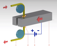
1 Wire. 2 Electrical discharge erosion (Electric arc). 3 Electrical potential. 4 Workpiece
In wire electrical discharge machining (WEDM), likewise known as wire-cut EDM and wire cutting,[30] a thin single-strand metal wire, usually brass, is fed through the workpiece, submerged in a tank of dielectric fluid, typically deionized h2o.[28] Wire-cut EDM is typically used to cut plates as thick equally 300mm and to brand punches, tools, and dies from hard metals that are difficult to automobile with other methods. The wire, which is constantly fed from a spool, is held between upper and lower diamond guides which is centered in a h2o nozzle caput. The guides, usually CNC-controlled, move in the x–y plane. On most machines, the upper guide tin can besides move independently in the z–u–v axis, giving rise to the ability to cut tapered and transitioning shapes (circle on the lesser, square at the top for instance). The upper guide can control axis movements in the GCode standard, x–y–u–5–i–j–grand–50–. This allows the wire-cut EDM to be programmed to cut very intricate and delicate shapes. The upper and lower diamond guides are unremarkably authentic to 0.004 mm (0.16 mils), and can accept a cutting path or kerf as pocket-sized as 0.021 mm (0.83 mils) using Ø 0.02 mm (0.79 mils) wire, though the average cut kerf that achieves the best economic price and machining time is 0.335 mm (thirteen.2 mils) using Ø 0.25 mm (9.viii mils) brass wire. The reason that the cutting width is greater than the width of the wire is considering sparking occurs from the sides of the wire to the work slice, causing erosion.[28] This "overcut" is necessary, for many applications information technology is adequately predictable and therefore can be compensated for (for example in micro-EDM this is not oft the case). Spools of wire are long — an 8 kg spool of 0.25 mm wire is simply over 19 kilometers in length. Wire diameter tin be as small as twenty μm (0.79 mils) and the geometry precision is not far from ± ane μm (0.039 mils). The wire-cut process uses water as its dielectric fluid, controlling its resistivity and other electric properties with filters and PID controlled de-ionizer units. The h2o flushes the cutting debris away from the cutting zone. Flushing is an important cistron in determining the maximum feed rate for a given material thickness. Along with tighter tolerances, multi centrality EDM wire-cutting machining centers take added features such as multi heads for cutting 2 parts at the aforementioned fourth dimension, controls for preventing wire breakage, automated self-threading features in case of wire breakage, and programmable machining strategies to optimize the functioning. Wire-cutting EDM is usually used when low balance stresses are desired, considering information technology does not require high cut forces for removal of material. If the energy/power per pulse is relatively low (as in finishing operations), little change in the mechanical properties of a fabric is expected due to these low residual stresses, although material that hasn't been stress-relieved can distort in the machining process. The work piece may undergo a significant thermal wheel, its severity depending on the technological parameters used. Such thermal cycles may cause formation of a recast layer on the part and residual tensile stresses on the work slice. If machining takes place after oestrus treatment, dimensional accuracy will non be affected by heat treat distortion.[31]
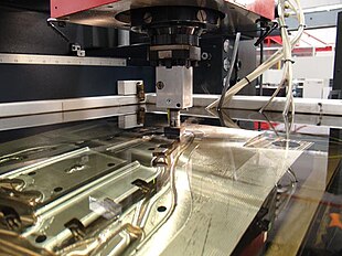
Fast pigsty drilling EDM [edit]
Fast hole drilling EDM was designed for producing fast, accurate, pocket-size, and deep holes. Information technology is conceptually alike to sinker EDM merely the electrode is a rotating tube carrying a pressurized jet of dielectric fluid. Information technology tin can brand a hole an inch deep in nearly a infinitesimal and is a good way to car holes in materials too difficult for twist-drill machining. This EDM drilling type is used largely in the aerospace industry, producing cooling holes into aero blades and other components. It is also used to drill holes in industrial gas turbine blades, in molds and dies, and in bearings.
Applications [edit]
Image production [edit]
The EDM procedure is well-nigh widely used by the mold-making, tool, and die industries, but is becoming a common method of making prototype and product parts, especially in the aerospace, machine and electronics industries in which production quantities are relatively low. In sinker EDM, a graphite, copper tungsten, or pure copper electrode is machined into the desired (negative) shape and fed into the workpiece on the end of a vertical ram.
Coinage dice making [edit]
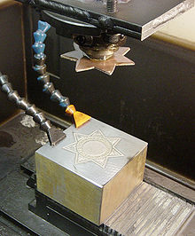
Main at peak, badge die workpiece at bottom, oil jets at left (oil has been drained). Initial flat stamping will exist "dapped", see sinking (metalworking), to give a curved surface.
For the creation of dies for producing jewelry and badges, or blanking and piercing (through use of a pancake die) past the coinage (stamping) process, the positive master may exist made from sterling silver, since (with advisable machine settings) the master is significantly eroded and is used just once. The resultant negative dice is and then hardened and used in a driblet hammer to produce stamped flats from cutout sail blanks of bronze, silver, or low proof gold blend. For badges these flats may be further shaped to a curved surface past another dice. This type of EDM is unremarkably performed submerged in an oil-based dielectric. The finished object may exist further refined by hard (glass) or soft (paint) enameling, or electroplated with pure gilt or nickel. Softer materials such as silver may be hand engraved as a refinement.
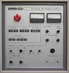
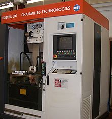
EDM control panel (Hansvedt machine). Machine may be adjusted for a refined surface (electropolish) at end of process.
Small-scale pigsty drilling [edit]

Small hole drilling EDM machines.
Small hole drilling EDM is used in a variety of applications.
On wire-cut EDM machines, small hole drilling EDM is used to make a through hole in a workpiece through which to thread the wire for the wire-cut EDM operation. A separate EDM head specifically for small hole drilling is mounted on a wire-cutting motorcar and allows large hardened plates to have finished parts eroded from them every bit needed and without pre-drilling.
Small pigsty EDM is used to drill rows of holes into the leading and trailing edges of turbine blades used in jet engines. Gas flow through these small holes allows the engines to apply higher temperatures than otherwise possible. The high-temperature, very hard, single crystal alloys employed in these blades makes conventional machining of these holes with high aspect ratio extremely difficult, if not incommunicable.
Modest hole EDM is also used to create microscopic orifices for fuel system components, spinnerets for synthetic fibers such equally rayon, and other applications.
In that location are as well stand-lonely pocket-size hole drilling EDM machines with an 10–y centrality also known as a super drill or hole popper that can auto blind or through holes. EDM drills bore holes with a long brass or copper tube electrode that rotates in a chuck with a abiding catamenia of distilled or deionized water flowing through the electrode equally a flushing agent and dielectric. The electrode tubes operate like the wire in wire-cut EDM machines, having a spark gap and wear rate. Some minor-hole drilling EDMs are able to drill through 100 mm of soft or hardened steel in less than ten seconds, averaging 50% to 80% clothing rate. Holes of 0.3 mm to six.ane mm tin can be achieved in this drilling functioning. Brass electrodes are easier to automobile only are non recommended for wire-cut operations due to eroded brass particles causing "contumely on brass" wire breakage, therefore copper is recommended.
Metal disintegration machining [edit]
Several manufacturers produce EDM machines for the specific purpose of removing broken cutting tools and fasteners from work pieces. In this application, the process is termed "metal disintegration machining" or MDM. The metal disintegration process removes just the center of the broken tool or fastener, leaving the pigsty intact and allowing a part to be reclaimed.
Airtight loop manufacturing [edit]
Airtight loop manufacturing can improve the accuracy and reduce the tool costs
Advantages and disadvantages [edit]
EDM is often compared to Electrochemical Machining.[32] Advantages of EDM include:
- Ability to automobile complex shapes that would otherwise exist hard to produce with conventional cutting tools.
- Machining of extremely hard fabric to very shut tolerances.
- Very pocket-size piece of work pieces can be machined where conventional cutting tools may damage the function from excess cutting tool pressure.
- There is no direct contact between tool and work slice. Therefore, delicate sections and weak materials can be machined without perceivable distortion.
- A good surface end tin can exist obtained; a very good surface may be obtained by redundant finishing paths.
- Very fine holes can be attained.
- Tapered holes may be produced.
- Piping or container internal contours and internal corners down to R .001".
Disadvantages of EDM include:
- Difficulty finding expert machinists.
- The slow charge per unit of cloth removal.
- Potential fire hazard associated with utilise of combustible oil based dielectrics.
- The boosted time and price used for creating electrodes for ram/sinker EDM.
- Reproducing sharp corners on the workpiece is difficult due to electrode habiliment.
- Specific power consumption is very high.
- Ability consumption is high.
- "Overcut" is formed.
- Excessive tool wear occurs during machining.
- Electrically non-conductive materials can exist machined simply with specific set-up of the process.[33]
See also [edit]
- Electro chemical machining
References [edit]
- ^ Jameson 2001, p. 1.
- ^ Jameson 2001, p. eight.
- ^ Lazarenko, B.R.; Mikhailov, V.V.; Gitlevich, A.East.; Verkhoturov, A.D.; Anfimov, I.S. "Distribution of elements in surface layers during electric spark alloying. (Raspredelenie Elementov V Poverkhnostnykh Sloyakh Pri Elektroiskrovom Legirovanii)". Surf. Eng. Appl. Electrochem. (Elektronnaya Obrabotka Materialov). 1977, 3: 28–33.
{{cite journal}}: CS1 maint: multiple names: authors list (link) - ^ Lazarenko, B.R.; Duradzhi, V.Northward.; Bryantsev, I.V. "Effect of Incorporating an additional inductance on the characteristics of anode and cathode processes. (O Vliyanii Vklyucheniya Dopolnitel'noi Induktivnosti Na Kharakteristiki Anodnogo I Katodnogo Protsessov)". Surf. Eng. Appl. Electrochem. (Elektronnaya Obrabotka Materialov). 1979, 5: 8–13.
{{cite periodical}}: CS1 maint: multiple names: authors list (link) - ^ Lazarenko, B.R.; Lazarenko, Due north.I. "Electric spark machining of metals in water and electrolytes. (Elektroiskrovaya Obrabotka Metallov V Vode I Elektrolitakh)". Surf. Eng. Appl. Electrochem. (Elektronnaya Obrabotka Materialov). 1980, 1: v–viii.
{{cite periodical}}: CS1 maint: multiple names: authors list (link) - ^ Krar, Stephen F.; Gill, Arthur R. (2003). Exploring advanced manufacturing technologies (1st ed.). Industrial Printing. p. half-dozen.2.one. ISBN0831131500.
- ^ Jameson 2001, pp. x–12.
- ^ Dulebohn, "Tracer controlled machining by electrically induced erosion", U.South. Patent 3,614,372, filed 4 December 1969, issued nineteen October 1971.
- ^ Jameson 2001, pp. 12–17.
- ^ a b c Rogers, Barry (2018), "The Remarkable Abilities of Wire EDM", TechSpex , retrieved 2018-05-21 .
- ^ Mohri, N.; Fukuzawa, Y.; Tani, T.; Saito, N.; Furutani, M. (1996). "Profitable Electrode Method for Machining Insulating Ceramics". CIRP Annals - Manufacturing Applied science. 45: 201–204. doi:10.1016/S0007-8506(07)63047-9.
- ^ Liu, Y. H.; Li, 10. P.; Ji, R. J.; Yu, L. L.; Zhang, H. F.; Li, Q. Y. (2008). "Result of technological parameter on the procedure performance for electric belch milling of insulating Al2O3 ceramic". Periodical of Materials Processing Applied science. 208 (1–iii): 245–250. doi:10.1016/j.jmatprotec.2007.12.143.
- ^ Morgan, C. J.; Vallance, R. R.; Marsh, Eastward. R. (2004). "Micro machining glass with polycrystalline diamond tools shaped past micro electro discharge machining". Journal of Micromechanics and Microengineering. 14 (12): 1687. Bibcode:2004JMiMi..14.1687M. doi:10.1088/0960-1317/xiv/12/013.
- ^ McCarthy, Willard J. and McGeough, Joseph A. "Motorcar tool". Encyclopædia Britannica
- ^ a b c d Descoeudres, Antoine (2006). Characterization of electric discharge machining plasmas. Thèse EPFL, no 3542.
- ^ Weng, F. T.; Shyu, R. F.; Hsu, C. Due south. (2003). "Fabrication of micro-electrodes past multi-EDM grinding procedure". Journal of Materials Processing Technology. 140 (ane–three): 332–334. doi:ten.1016/S0924-0136(03)00748-nine.
- ^ Narasimhan, J.; Yu, Z.; Rajurkar, 1000. P. (2005). "Tool Wear Bounty and Path Generation in Micro and Macro EDM". Journal of Manufacturing Processes. 7: 75–82. doi:10.1016/S1526-6125(05)70084-0.
- ^ Koelsch, James (October 2009). "EDM: A Changing Competitive Calculus," Manufacturing Engineering, Society of Manufacturing Engineers
- ^ Han, F.; Chen, L.; Yu, D.; Zhou, Ten. (2006). "Basic study on pulse generator for micro-EDM". The International Periodical of Avant-garde Manufacturing Engineering science. 33 (5–6): 474. doi:ten.1007/s00170-006-0483-ix. S2CID 110776709.
- ^ a b c d eastward Ferri, C.; Ivanov, A.; Petrelli, A. (2008). "Electric measurements in µ-EDM" (PDF). Journal of Micromechanics and Microengineering. 18 (8): 085007. Bibcode:2008JMiMi..18h5007F. doi:10.1088/0960-1317/18/8/085007.
- ^ Van Dijck, Frans (1973). Physico-mathematical analysis of the electro discharge machining process. PhD Thesis Katholieke Universiteit Leuven.
- ^ a b Dibitonto, D. D.; Eubank, P. T.; Patel, M. R.; Barrufet, 1000. A. (1989). "Theoretical models of the electrical discharge machining procedure. I. A uncomplicated cathode erosion model". Journal of Applied Physics. 66 (9): 4095. Bibcode:1989JAP....66.4095D. doi:10.1063/1.343994.
- ^ a b Patel, M. R.; Barrufet, M. A.; Eubank, P. T.; Dibitonto, D. D. (1989). "Theoretical models of the electrical discharge machining procedure. 2. The anode erosion model". Journal of Applied Physics. 66 (9): 4104. Bibcode:1989JAP....66.4104P. doi:x.1063/1.343995.
- ^ a b Eubank, P. T.; Patel, One thousand. R.; Barrufet, M. A.; Bozkurt, B. (1993). "Theoretical models of the electric discharge machining process. III. The variable mass, cylindrical plasma model". Periodical of Applied Physics. 73 (11): 7900. Bibcode:1993JAP....73.7900E. doi:10.1063/ane.353942.
- ^ Singh, A.; Ghosh, A. (1999). "A thermo-electric model of material removal during electrical belch machining". International Journal of Machine Tools and Manufacture. 39 (4): 669. doi:10.1016/S0890-6955(98)00047-ix.
- ^ Vishal Kumar Jaiswal (2018) Literature Review on Electrical Belch Machining (EDM)."International Journal for Scientific Inquiry and Development 6.5 (2018): 239-241, IJSRD http://world wide web.ijsrd.com/articles/IJSRDV6I50198.pdf
- ^ Bilstein, Roger E. (1999). Stages to Saturn: A Technological History of the Apollo/Saturn Launch Vehicle (NASA-SP4206). DIANE Publishing. p. 145. ISBN9780788181863.
- ^ a b c d east Jameson 2001.
- ^ Semon, G. (1975). A Practical Guide to Electro-Discharge Machining, 2d ed. Ateliers des Charmilles, Geneva.
- ^ Todd, Robert H.; Allen, Dell Thou.; Alting, Leo (1994). Manufacturing Processes Reference Guide. Industrial Press Inc. pp. 175–179. ISBN0-8311-3049-0.
- ^ ELECTRICAL Discharge MACHINING (EDM). header.com
- ^ "Comparing EDM and Electrochemical Machining". May 2021.
- ^ Kucukturk, K.; Cogun, C. (2010). "A New Method for Machining of Electrically Nonconductive Workpieces Using Electric Discharge Machining Technique". Machining Science and Technology. 14 (2): 189. doi:10.1080/10910344.2010.500497. S2CID 138552270. (2010).
Bibliography [edit]
Jameson, East. C. (2001). Electric Discharge Machining. SME. ISBN978-0-87263-521-0. Archived from the original on 2011-09-28.
External links [edit]
- New Arc Detection Engineering science for Highly Efficient Electro-Discharge Machining
- Engineering Design For Electrical Belch Machining
DOWNLOAD HERE
Posted by: carstenstond1961.blogspot.com


0 Komentar
Post a Comment